lab06 : Basics of electronics with Raspberry Pi
| num | ready? | description | assigned | due |
|---|---|---|---|---|
| lab06 | true | Basics of electronics with Raspberry Pi | Mon 08/19 04:25PM | Tue 08/27 02:45PM |
If you find typos or problems with the lab instructions, please report them on Piazza
Learning objectives
In this lab you will be introduced to the basics of electronics using a a credit-card sized computer called the Raspberry Pi. You will build simple electronic circuits and write programs to control them. Because this lab requires special hardware, which we need to share amongst groups, you only have limited time to work on this assignment. If you are not able to get all the way to the end, don’t worry. The main goal is to learn and have fun.
Getting started
Observe your Raspberry Pi
Take a look at the Raspberry Pi (or RPi for short) on your workbench. You are looking at the insides of a computer. Your gut feeling may be that it all looks very complex. Your premonitions are not misplaced. The circuit that you are looking at is not called the motherboard for nothing.
The green base on which all the electronic components (which you see as bulgy entities) are laid out is a non-conductive substrate. This means that the green parts of the board don’t conduct electricity. However, to connect the various electrical components, conductive tracks made of copper are etched on the green base. At the very center of your RPi sits a prominent black square block. This is the brain of your RPi: the processor (a 64-bit Quadcore ARM). On the back you’ll find another black block, which holds 1GB of RAM (Random Access Memory). For now, just know that the RAM is a form of non-persistent memory. There are other components on the RPi. To identify them orient your RPi to match the circuit below.
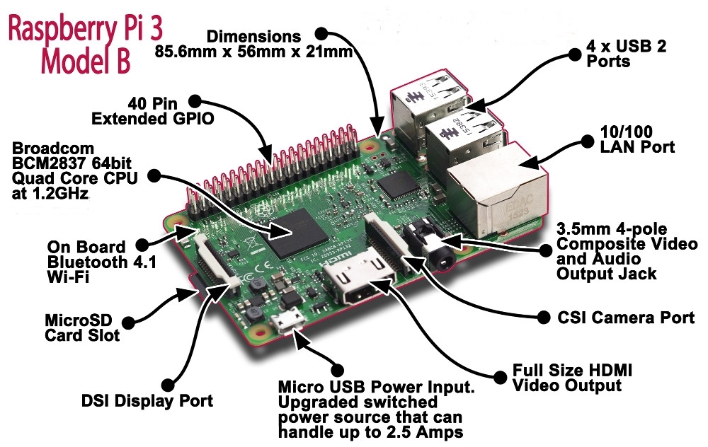
Observe the components marked in this diagram on your RPi. We will focus on a few important components on the diagram:
-
Internet connectivity: The RPi can get Internet connectivity through the LAN port (Ehternet), or throught the built-in WiFi chip. In our setup, we will use the WiFi.
-
USB ports: The RPi3 comes with four USB ports. We will use them to connect a mouse and keyboard.
-
HDMI (High Definition Multimedia Interface) Video Output: This is an interface that connects your RPi to a monitor.
-
MicroSD card slot: All the software that runs on the RPi, which includes the Operating System (more on the OS later) as well as your programs, will be stored on the SD card that goes into the SD card slot. The SD card is essentially the Hard Drive of the RPi.
-
GPIO pins: This stands for General Purpose Input / Output. You won’t be able to observe the GPIO pins on the Raspberry Pi on your workbench because they are hidden under the ribbon cable that connects them to the white breadboard. These pins can be configured to send/receive signals through your Python programs. You will control and sense the world around you through these pins.
-
Micro USB Power Input: Using this input you can power up your RPi using a wall charger or a battery.
Observe the connections from your RPi to other peripherals
In the setup provided to you, the RPi has been wired to work as a desktop computer. Actually, it’s more than a desktop because it is set up to connect to an electronic circuit that you will soon create (something you can’t do with standard desktops). For the robotics projects, we will operate the RPi in an untethered fashion (so the robot can be mobile) but for now observe the following wired connections from the RPi to other peripherals:
- The RPi has a connection to a monitor via the HDMI port.
- The keyboard and mouse are connected via USB.
- The RPi is powered up using a charger that is plugged into the wall.
- The GPIO pins on the RPi are routed to a breadboard via a ribbon cable.
Note: It is best to plug or unplug peripherals when the RPi is shut down. This minimizes the risk of the device resetting, which in turn could causes corrupting the SD card
Now let’s take a closer look at the breadboard and the GPIO breakout board that sits on it. You will need this information to complete the later exercises in this lab.
The breadboard
The RPi chip itself is very small, so we will be attaching an electronic component called a breadboard – which is designed to make it possible to experiment with circuits by extending the available space. For electricity to flow you need connections. Think of a breadboard as a way of giving you more space to make those connections. The main feature of the breadboard is that it comes with a set of in-built electrical connections which significantly simplifies the wiring involved in complicated circuits. Let’s try to understand the electrical connections on the breadboard using the figures below:
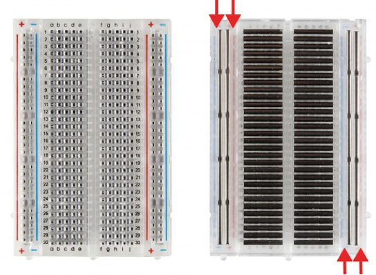
The figure on the left shows a picture of the breadboard as visible to you, while the one on the right shows in internal electrical connections when the back of the breadboard is uncovered. The rows are numbered 1 through 30 and the columns ‘a’ through ‘j’. In the figure on the right observe how the conductive metal strips run across the rows. This means that any two grids that are on columns ‘a’ through ‘e’ are at the same potential as long as they are also on the same row. Similarly, any two grids that are on columns ‘f’ through ‘j’ are at the same potential as long as they are also on the same row. However, the two halves of a row are electronically disconnected. As you will see, this helps you out a lot.
Are each of the following grids internally connected on the above shown breadboard?
- 1a and 2a
- 1a and 1b
- 1a and 2b
- 14c and 14f
- 1j and 2j
- 1a and 1e
Finally, the breadboard has two vertical lines running up and down on both sides. The pins on each of these lines are electrically connected but the lines are electrically disconnected from each other. The convention is to connect a positive voltage (3.3V pin) to the line that has a ‘+’ sign above it and connect the ‘ground’ (GND pin) to the line with the ‘-‘ sign above it.
The GPIO pin numbering conventions
The Raspberry Pi 3, model B (which is the one we are using) has 40 GPIO pins that are laid out as two rows of 20 pins each, also depicted in the diagram below:
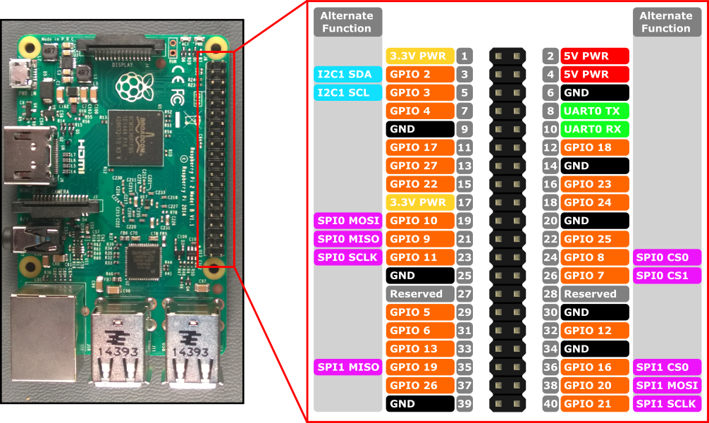
The pins that are colored in orange are available for any general purpose and can be referred to and configured in your python programs. Some of these orange pins have an ‘alternate function’ as well; this means they may not be available if you are using that alternate function. In case you are not sure, avoid those pins and only use the orange colored ones that do not have an alternate function. There are two different conventions used to refer to these pins:
-
Physical location (board convention): One way is to just refer to the pins based on their physical location. These numbers are indicated in the gray boxes in the above diagram. All pins on the left half have odd number locations while all pins on the right half have even numbered locations.
-
BCM (broadcom convention): You can also use the broadcomm convention where the numbering is not based on the physical location. For example the pin at physical location 12 is referred to as pin number 18 (note that you drop the ‘GPIO’ part) as per the BCM convention.
Either of the above conventions is okay to use in your programs as long as you define which scheme you are using before you start referring to the pins.
Note that physical pins 1 and 17 provide 3.3V, while physical pins 2 and 4 provide 5V. Physical pins 6, 9, 14, 20 and 25 provide the ground (GND) signal which is also very important in your circuits.
The GPIO breakout board shown below makes all these pins available to you on a breadboard where you will be doing your electrical wiring.
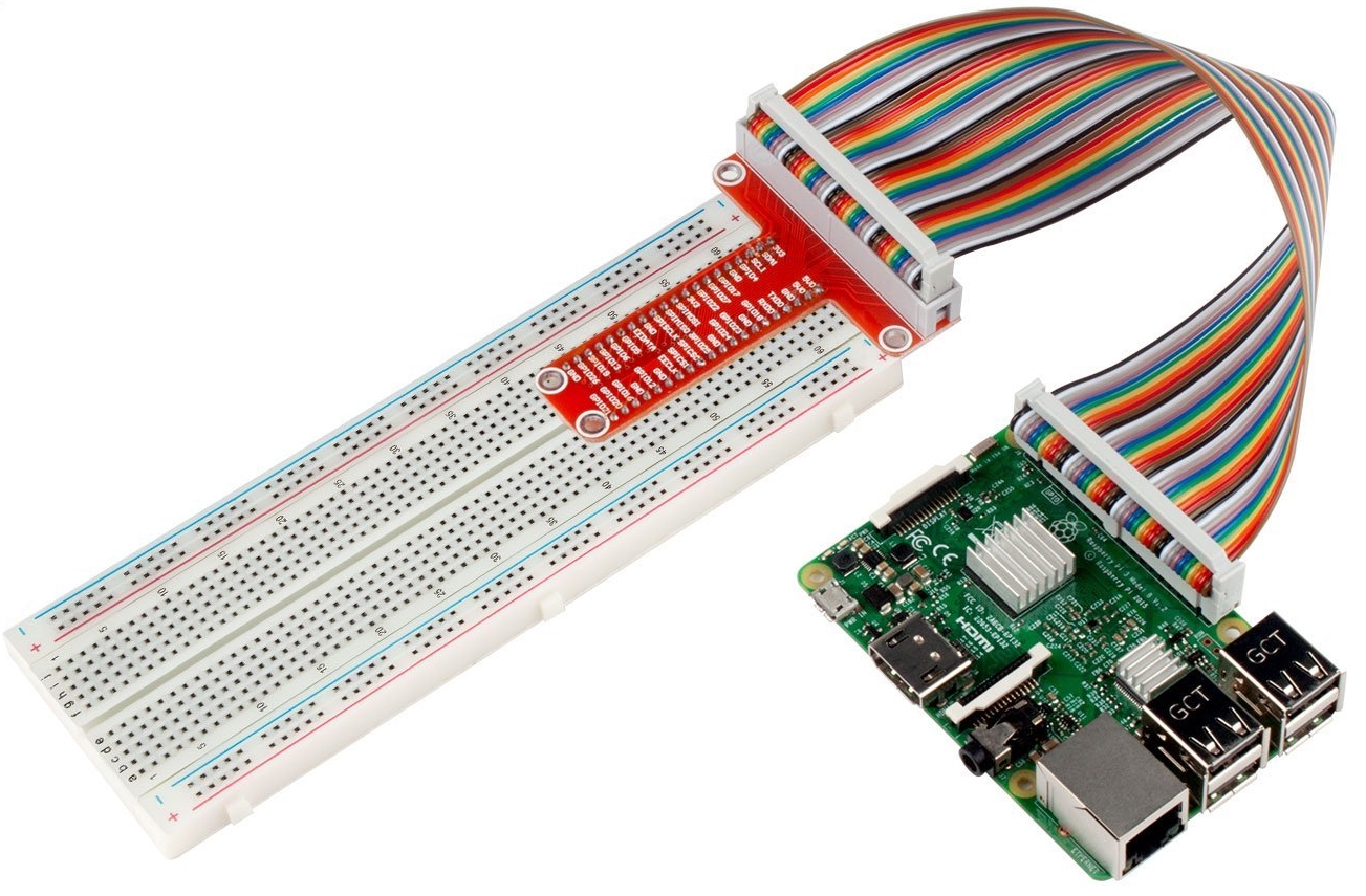
The labels on the breakout board use the BCM naming convention. However, we have connected the breakout board in such a way that you can easily derive the physical pin number of any pin by looking at the row number that it is connected to on the breadboard.
Getting to know your desktop environment
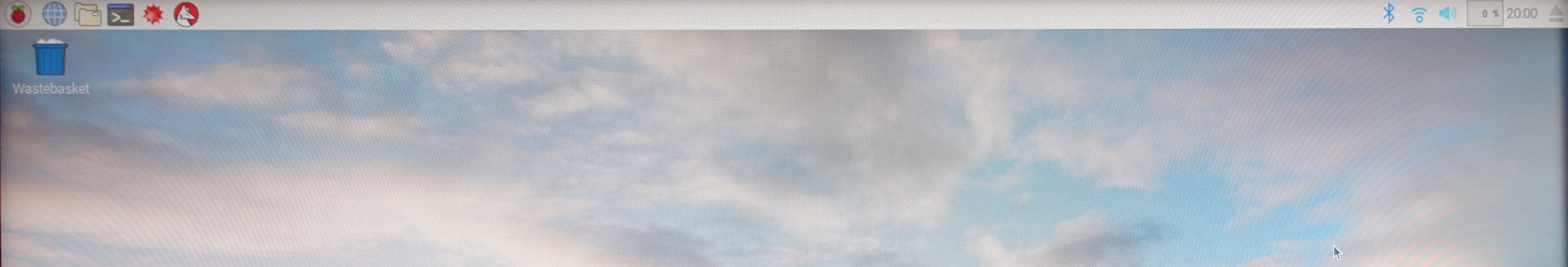
The operating system on the RPi is a version of Linux known as Raspbian. The picture above shows the Pixel desktop environment under Raspbian. Feel free to poke around and see what all of these icons mean.
Terminal
Terminal is the command line interpreter. It is the icon on the top bar showing >_. Click it to open. You can also find it under the Accessories submenu of the main menu (the raspberry icon).
When you open Terminal, notice the prompt says pi@XXXX. This means that you are user pi and the name of your machine is XXXX.
All the unix commands that you have learned so far can be used to navigate through the file system on your RPi. You can also use command line git just like how you would on the ieng6 machines.
WiFi
To see if your RPi is connected to the WiFi already or not, click the WiFi icon in the top right corner. Check if it indicates that you are connected to the UCSD-Protected network. If it does not, follow the steps below.
To connect to the WiFi network, click on the program “wifisetup.sh” on the desktop. In the window that pops up, select “Execute in Terminal”. This will open a terminal window that prompts you for your wifi username and password (the one you use for UCSD-Protected). After you enter this information, your RPi will automatically reboot. When it is done rebooting and you are back to your desktop environment, check the WiFi icon again and verify that you are now connected to UCSD-Protected (it may take a few minutes).
While not necessary for this lab, if you want to know the IP address of your RPi, open a Terminal window and type:
ifconfig
It will show you a bunch of information, organized in three sections. In the bottom section, labeled wlan0, look for inet addr. The numbers that follow (something like 192.168.1.233) are your IP address. Knowing this will come in handy if you want to log in remotely using ssh.
Create a git repo and get the starter code
Use a web browser on your laptop or the RPi to create a new repo on github.com called spis19-lab06-Name-Name, for example using Method 1. When creating the repo import the starter code from this git repo: https://github.com/ucsd-cse-spis-2019/lab06-startercode.git.
Note that you must keep your git repo updated with the latest version of your code because your code will be erased from the RPi at the end of the lab session. This is to ensure that the hardware is ready for use by the next group. So don’t forget to push your code to the online repo at the end of the lab. However, you should push your code repeatedly during the lab. If you accidentally wire things up wrong, you may reset the RPi. This could result in a corrupted SD card, meaning all your data was lost. So back up to github frequently.
Set up your programming environment
- Configure your git credentials on the RPi. In the home directory
/home/pitype the following commands replacing the name and email credentials with yours.
 git config --global user.name "Bert Sesame"
 git config --global user.email bsesame@eng.ucsd.edu
- Clone your git repo over https into your home directory on the RPi. DO NOT log into the ieng6 machines and try to do this step there. To clone your repo first open a browser on the RPi (or your laptop), and navigate to your repo on github which should be called
spis19-lab06-Name-Name. Go to the green button that says ‘clone or download’ and get the https address of your repo. The https address should be something likehttps://github.com/ucsd-cse-spis-2019/spis19-lab06-Name-Name.git. Do not use the ssh address as you have in the past.
Make sure you have the starter code in your repo. If you did not import the starter code when creating the repo, ask the mentors for help.
On RPi, you can edit Python code using gVim just like you did before. To execute your code, use:
python3 <filename>
Here, replace
You are now ready to start working on your first exercise where you will create your own circuit and control it using the starter code given to you.
Making an LED blink
In this exercise you will create a circuit consisting of an LED and a resistor connected to the RPi. You will then periodically blink the LED using the example program provided to you in the starter code.
For all your work with Raspberry Pi, it is extremely important you do not make short circuit connections on the GPIO pins. A short circuit is when a supply or GPIO pin set to HIGH is directly connected to a GND or GPIO pin set to LOW. If you are unsure, ask a mentor or instructor to check your circuit before running your program. Always be extremely careful to avoid short circuits. It may reset the RPi, which can corrupt the SD card or possibly even destroy the RPi.
Understanding the code
In gVim open the file 01_blinking_LED.py. Let’s begin by trying to understand the given code.
The first two statements import the modules needed for this exercise:
import RPi.GPIO as GPIO
import time
The RPi.GPIO module provides routines for configuring the GPIO pins on the RPi and for sending and receiving signals on these pins. Since the GPIO pins are digital we can only send high or low voltages.
The time module provides routines that make use of the clock on the RPi. Using the time module you can make the RPi wait for some time before executing the next python command in your program. For example, time.sleep(0.5) makes your program wait for half a second before moving on to the next line of code.
The lines immediately after the import statements take care of configurations related to using the GPIO pins. The first one specifies that we are using the physical numbering scheme.
GPIO.setmode(GPIO.BOARD)
If we chose to use the BCM scheme, that line should be replaced by the following:
GPIO.setmode(GPIO.BCM)
Before proceeding further, identify pin number 11 on your breadboard (remember, we are using physical numbering, so you will need to count the pins to find the location of pin 11). You will need this for wiring your circuit.
The Python GPIO library allows configuring certain pins to be either input or output pins using the setup(Pin, mode) function, where Pin is the pin number and mode is either GPIO.OUT (for output) or GPIO.IN (for input). If we want our program to generate high or low voltages on a pin that potentially drives other electronic components (such as LEDs or servos), then configure the pin to be an OUTPUT pin. If we want to read the signal generated by sensors into our program, then configure the pin to be an INPUT pin.
In our code here, pin number 11 is configured to be an output pin using the command GPIO.setup(LedPin, GPIO.OUT). It also sets the initial state of that pin to be LOW via the command GPIO.output(LedPin, GPIO.LOW).
After these inital settings and definitions comes the main program. For now ignore the try …except structure. The key part of the code is the while True: loop. The code in this loop contains the main functionality and runs forever. Any ideas why we are doing this?
Wiring the circuit
To create the circuit you will need the following components
- One LED (any color)
- Two wires
- One 100 ohm resistor (the resistor with bands colored brown, black, black, black, brown or something similar). The colored bands on the resistor encode the resistor value. A good explanation of how to decipher this code is given on this website.
The picture of an LED and the symbol used for it in circuits is shown below:

The longer leg of the LED is called the ‘anode’ and the shorter leg is called the ‘cathode’. When there is a positive voltage difference between the anode and the cathode, the LED is forward biased or “on state” and current flows through the circuit lighting it up, otherwise the LED is in the “off state”.
Wire up the circuit shown by the following diagram. Remember: we are using physical pin numbering for the RPi. You should use jumper wires and the breadboard to make the physical connections.
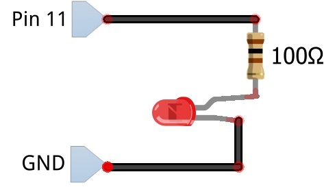
Ask an instructor or mentor is you don’t understand the diagram. For a more in depth information on configuring GPIO pins as outputs refer to this website.
Now, run the 01_blinking_LED.py program. Hopefully you should have a blinking LED. To stop the program, press ‘Ctrl+C’ on the keyboard. This will force the code the execute the KeyboardInterrupt: portion.
If you were unsuccessful, the problem is most likely with your wiring. If you were successful, take a close look at the code.
Now, modify the program (and rename it to 01_blinking_LED_sol.py) to double the frequency at which the LED blinks. Make sure you commit this code to your github repo.
Note: It may happen at some point that you get an error or warning that says “This channel is already in use”. This is Python telling you that one of the GPIO pins you are trying to use is already assigned to another program. This can happen when you ran your code before and it was exited without executing the GPIO.cleanup() line in the KeyboardInterrupt portion (e.g., it stopped because there was an error in the code). If it doesn’t execute GPIO.cleanup(), it never gives up control of the GPIO pins, and so when the next program tries to use it, there may be a conflict. If all you get is a warning, you can ignore it. If you get an error and your code cannot be executed, put GPIO.cleanup() in your code immediately after importing the libraries. This should resolve the issue, and you can then comment out this line going forward.
Controlling an LED using a button
Next, we are going one step further and we’ll use a button to control the LED. You don’t need to undo the wiring you already created for the previous problem. This can stay the same. We will just add circuitry for a button.
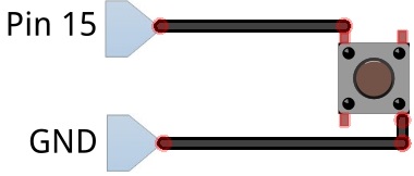
Buttons are switches that are used to connect or disconnect circuits. In the figure below, pins pointed out by the arrows of the same color are internally connected. When the button is pressed, the pins indicated by the blue arrow will connect to the pins indicated by the red arrow.

Understanding how to use a button
Now, let’s start wiring the circuit. You should keep the LED circuit from the precious exercise. Then add the button as per the circuit diagram below.
Next, open the program 02_buttonLED.py in gVim. One of the key differences in this exercise compared to the previous one is that you will configure the pin connected to the button as an INPUT pin. Here is a nice excerpt from a website explaining such a configuration:
A GPIO pin configured as an input is used to read (to input) the value of one digital signal. In this case the pin is converting the voltage being delivered to the pin into a logical value of 0 or 1 for subsequent use in the program. By convention, when the voltage on the pin is ‘high’ (near Vcc), reading the pin will result in reading a logic 1, while when the voltage is ‘low’ (near GND), reading the pin will result in reading a logic 0.
So, the bottom line is that when we configure a GPIO pin as an input, we can read the voltage at that pin in our Python program.
But, what is the expected voltage if the pin is not connected to anything at all? This would occur in the button circuit we just built and the button is not pressed. The answer is that we really can’t say. When a GPIO pin is set as an input but is not connected to anything it is ‘floating’ and has no defined voltage level. For us to be able to reliably detect whether the input is high or low, we need to tie it so that it is always connected to something and either reads high or low. This can be done by using a pullup resistor, as shown in the diagram below. (If you are interested in exactly how this work, you can ask the instructors).
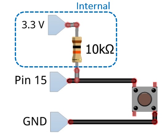
However, you don’t actually have to wire up a separate resistor in your circuit. Instead, the RPi has these pullup resistors internally built-in. You just have to specify in the software that you would like to use it. In the code, you will find the line:
GPIO.setup(BtnPin, GPIO.IN, pull_up_down = GPIO.PUD_UP)
This makes the BtnPin an input AND internally attaches the pullup resistor. Note that pulldown resistors are available as well. If you want to specify a pin as simply an input, without the pullup or pulldown resistor, you can write:
GPIO.setup(Pin, GPIO.IN)
Now, let’s have a closer look at the starter code. This program checks pin 15 (the pin connected to the button) and prints the status of that pin (1 indicates True or high voltage, 0 indicates False or a low voltage). It doesn’t do much more than that at the moment. You will need to modify the code so that the button presses control the led. However, before you do this, try to understand the starter code first. What do you expect the output to be?
Run the code. What do you get? Come up with a simple test to check the correctness of the program.
Controlling the LED
Now, it’s time to write some code of your own.
(1) Modify the program such that the LED is ON when the button is pressed and OFF when the button is not pressed. Name it 02_buttonLED_sol1.py and commit it to the github repo.
(2) Now change the functionality: toggle the LED every time the button is pressed. So, if the LED is ON and the button is pressed, it should turn OFF. If the LED is OFF and the button is pressed, it should turn ON. So pressing the button changes the state of the LED, from ON to OFF to ON to OFF etc. This functionality is trickier to obtain. You will need to think carefully how you can accomplish this. Name this version of your code 02_buttonLED_sol2.py and commit it to the github repo.
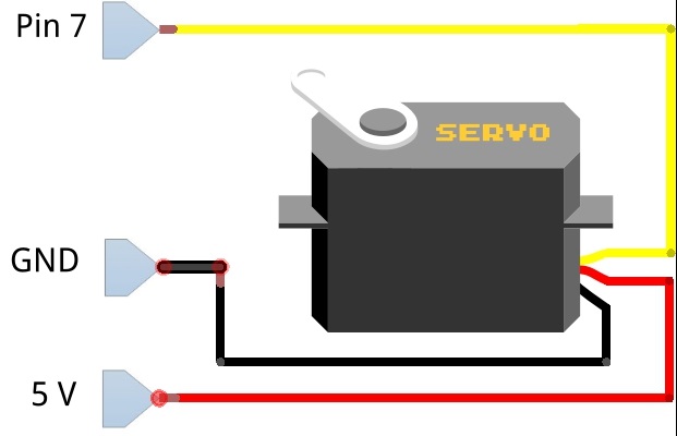
Controlling a servo motor
A servo is an electrical motor that comes with built-in control circuitry. There are two types of servos: standard servos and continuous rotation servos. In this lab, we will be working with standard servos. A stardard servo can move its arm half a rotation, from an angle of 0 degrees to an angle of 180 degrees, and back. Servos are used in a lot of applications, for example to control flaps and rudders of RC aircraft or to rotate camera turrets.
Keep the circuitry from the previous problems (the wiring of the LED and button), and add a servo. The extra wiring is shown in the diagram below.
Testing the servo
Now look at the starter code for the servo in 03_servo.py. The first few lines of code should look familiar to you: we are configuring pin 7 as an output as it will be used to control the servo. However, the control signal we will send to the servo is a PWM or Pulse Width Modulation signal. What this means is that it alternates between HIGH and LOW at a certain frequency. The percentage of time the signal is HIGH is called the duty cycle. By changing this duty cycle, we can signal to the servo to which angle we want it to move.
The program includes code between the comments #--- Start of the PWM setup --- and #--- End of the PWM setup --- that takes care of this signaling. It is not important to understand the details here. Just leave the code as is and realize that it takes care of the PWM signal generation. The only thing you really need to know is that it defines a function set_duty_cycle(angle). This function generates the PWM signal to tell the servo to move to the position indicated by ‘angle’ (between 0 and 180).
Try out the starter code. You should see the servo move between angle 0 and angle 180.
You will notice that the pwm_servo.start() command tells the servo to start moving to the new angle. The actual motion will take some time. This is why there are the time.sleep() commands: we want to halt the code execution long enough so that the servo can move to its desired destination. Specifically, time.sleep(x) is a function in the time library that halts execution for x seconds.
What happens when you reduce this sleep time? Try decreasing it to 0.8 seconds, 0.5 seconds, 0.1 second, etc. Can you explain what you observe?
Modifying how we implement delays
Next, open the starter code in 04_timing.py. This shows an alternative way for a program to delay execution without explicitly adding in sleep time with time.sleep(). Execute the code to verify its functionality. It prints a comment every second, but the way this delay is implemented is much more flexible than when using time.sleep(). Go through the code in detail and make sure you understand how it works.
Now, let’s use this knowledge to change the servo example code. These last two coding assignments will challenge your ability to think about real-time coding. If you are sturggling, don’t despair. Part of the goal is to realize the challenges that result from dealing with the concept of time in embedded systems. Thinking about functionality as a collections of states (as in Picobot. Remember that lab?) is very useful here. We also discuss this more in lecture. Just give it a shot and see what you can come up with.
(1) Modify the code from 03_servo.py to perform the same functionality, but without using time.sleep(). Instead, use the technique shown in 04_timing.py. Name this version of your code 03_servo_sol1.py and commit it to the github repo. The easiest way to get started may be to begin with the 04_timing.py code and copy in the servo functionality from 03_servo.py.
(2) Now, let’s modify the functionality a bit. The code you wrote in part (1) will allow you to do this. We want the servo to move as we did before, but we also add a button. As soon as the button is pressed, the servo should move back to position 0 and stay there as long as the button is pressed. Why would this be hard to implement if you use time.sleep()? Name this version of your code 03_servo_sol2.py and commit it to the github repo.
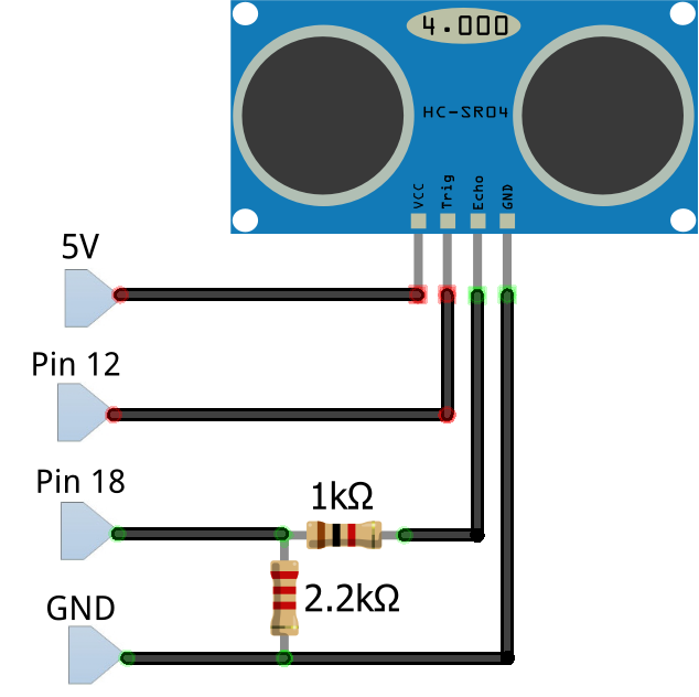
Reading from a distance sensor
An ultrasound distance sensor is able to detect the distance to an object by sending out an ultrasonic pulse and measuring how long it takes for the reflection to come back. With this two-way travel time and knowledge of the speed of sound, it can calculate the distance. This is pretty much how echo-location for bats works as well.
Keep the circuitry from the previous problems, and add an ultrasound sensor. The extra wiring is shown in the diagram below.
Testing the ultrasound sensor
Run the starter code 05_ultrasound.py. If successful, it will print the distances measured by the sensor every 0.5 seconds. If it prints -1, it means it was not able to detect an object in front of the sensor. The reason is that it only has a limited range.
Now have a close look at the code. Most of the interfacing with the sensor is in a helper function, which you shouldn’t modify. This function reads from the sensor and uses this reading to calculate the distance. If you are interested in the details, you can go through the code and also have a look at this [tutorial] (https://howtomechatronics.com/tutorials/arduino/ultrasonic-sensor-hc-sr04/). It is written for another embedded board, the Arduino, but the most interesting part for you is the description of how the sensor sends out sound signals to measure distance.
Implementing your own functionality
Now it is time to be creative with the ultrasound sensor. Modify the code to include an LED and have the LED blink at different rates based on the distance measured by the sensor. When the distance is smaller, the LED should blink faster. Make sure you include comments in your code to explain how the blinking rate depends on the distance.
Save this code as 05_ultrasound_sol1.py and commit it to the github repo.
Next, add code that also moves the servo to a position of x degrees (with x between 0 and 180), based on the measured distance. Again, make sure your comments explain this mapping.
Save this code as 05_ultrasound_sol2.py and commit it to the github repo.
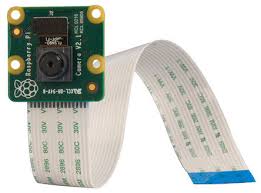
Trying out the picam camera
Very important: When you attach or remove the picam, your RPi needs to be shut down!!! Otherwise, you may damage the device.
We can attach a miniature camera that was specifically designed for the RPi, called the picam. You need to connect it to a dedicated port on the RPi with a flex cable. Remember, do not attach or remove the picam when the RPi is powered on. Shut it down first. Ask the mentors or instructors for help with this.
Once you have the picam attached, try out the program 06_picam_preview.py. This will open a preview window that automatically closes after 5 seconds. It is a good test to see if the camera is connected correctly and working properly. If you get an error stating something like “Camera is not enabled”, you need to go into the RPi configuration and enable it there and reboot. A mentor can help with this.
Next, run the program 06_picam_video.py. It will open two video windows. One with the original video, and one where the center part has inverted colors. Basically, this example shows how we can apply what we have learned about image processing to the RPi. All the image manipulations we did in that lab, we could implement here as well, but now on video streams. Note that for efficiency reasons, we are no longer using the PIL library here. Instead, we use the very powerful OpenCV (which stands for Open Computer Vision) library cv2. To store images, we will not do this in Image objects anymore (as PIL does), but instead we will be using numpy array objects. Calculations on these numpy arrays are much faster. Essentially, a numpy array is a 3-dimensional array of pixels: the first two dimensions are the x and y of the pixel and the third dimension is of size 3, containing the values of B, G, and R for that pixel. Numpy assumes the color channels are in the order BGR. For example, if img_np is a numpy array containing an image, then img_np(2,5,0) is the B value of the pixel at location x = 2, y = 5. Similarly, img_np(2,5,1) is the G value for the pixel at (2,5) and img_np(2,5,2) is the R value. For detailed information on numpy and how to manipulate these arrays, you can check out this [website] (https://docs.scipy.org/doc/numpy/user/quickstart.html).
Now you can try to modify the picam video starter code. What you decide to do is totally up to you. You could convert to grayscale, black our certain regions, mirror the image, look for a particular color, etc. Save your code as 06_picam_video_sol1.py and make sure you add comments to explain what it does. Upload to github.
We hope you enjoyed this lab and got a bit of a taster of what is possible with RPis and robotics …